
We’ve moved!
November 20, 2011 § Leave a comment
Using WordPress tools, the II Much Fabrication blog is now directly hosted at:
Fuel Tank
August 23, 2011 § 1 Comment
It’s been a while, but work on our Project Unfair is underway again. After my last project, I vowed not to ever use drag-racing parts for fuel delivery again. I was able to get that system to work most of the time, but eventually heat would cause cavitation, vapor-lock, and failure.
Instead, I worked with Carl Casanova at Vaporworx on our fuel tank. Unfair requires a wider range of fuel delivery than most cars since we’re expecting decent mileage while cruising, and 1200+ horsepower when running full-boogie for a quarter-mile pass or running the standing mile. As Carl calculated that means fuel needs range from 4 gallons per hour to 130 gallons per hour!
VaporWorx provides late-model GM fuel pump solutions to hot-rodders. These fuel modules, as GM refers to them, solve many problems. They are controllable by PWM (pulse-width modulation) and so can be slowed and sped up as the engine need changes. They also provide reservoirs to reduce cavitation, and can be hooked up to Walbro venturi pumps to literally be able to pump fuel to the last cupful in the tank.
Most of VaporWorx setups use a 5th gen Camaro pump, but that’s not quite up to the task, so we stepped up to a CTS-V pump. And that wasn’t enough, so we’re running two! VaporWorx has made some tweaks to their programming to support dual modules, along with setting a ramp-up method to support our crazy need to run 18 pounds of boost on race gas. Boost works against the fuel injectors: as the pressure increases, the injectors have to overcome it, so higher fuel rail pressure is needed. The VaporWorx controller takes all this into account. It’s an awesome solution to a difficult problem.
I built a fully-custom aluminum tank with dual pump module rings, fuel level sending unit boss, fill port to use a 67-68 style gas cap, vent, and drain ports. I’ll also be using our unique fuel tank vent/baffle along with a non-vented cap to control fuel slosh and gas fume emanation.


Floating Away
April 5, 2011 § Leave a comment
I’ve just finished up a major sub-system on our Project Unfair: our floating rear axle setup. It’s all about fixing the phenomenon of “knock back” , where the pedal goes to the floor after hard cornering due to rear axle deflection pushing the brake pads away from the rotor. Our Unfair solution is to use a circle-track full floating axle setup where the axle is de-coupled from the wheel hub and the rotor. Using some custom machined parts, I’ve hooked up Wilwood’s 14″ rear brake setup with a Moser GN floater. I still have some work for a parking brake, but this setup will completely prevent any knock back issues.
Welding Center
March 15, 2011 § Leave a comment
I’ve been using my new Miller welders for about a month now. I’m pleased so far… the Dynasty 200 DX TIG machine has an amazing arc and the foot pedal felt natural from the start. I’m also applying my new knowledge of proper setup when using a gas lens (use 22 CFH rather than 16ish). Now I can use a tungsten stickout of an inch with no problem at all. Check out the size of the machine in the photo below. It weighs less than 50 lbs, and can be carried to the job site. It will even work with 110V if needed. I still haven’t tried it out on aluminum — which is why I sold my Lincoln to step up to this machine in the first place. That’s going to change soon: I’ve got a fuel tank to make in a couple of weeks.
My new Miller MIG machine (Millermatic 211) was a bit more trouble. Using the factory setup wasn’t working — I was struggling with burnback (where the wire melts at the torch end and not in the weld puddle) until I read on the Miller welding forum to turn up wire speed about 20% when using .024 wire (which I was). Now the machine is rock-solid and works perfectly. The low-spatter claims seem to be true as well.

Two U-joints are better than four
February 11, 2011 § Leave a comment
I’m working on getting the human interfaces fabricated on Project Unfair and I just finished mocking up the column connection to the steering servo. Wilwood pedals are coming next, or possibly mounting the seat. The neat thing about this steering shaft is that my original design used 4 U-joints with the steering shaft under the motor mount, but Tim Christ at Coast Chassis Design (the gods of 10.5 racing over in Daytona Beach) convinced to look into rotating the rack so the servo pointed above the motor mount.
So I did, and here’s the result. A very clean 2 U-joint steering mechanism. Good stuff. This photo is of the mockup with steel U-joints… we have ultra-cool aluminum versions from Borgeson on the way.

Setting up for Humans
February 6, 2011 § Leave a comment
I’ve just finished a little project on Project Unfair that needed to be done to get to my next big project. In order to mount the seats, steering wheel, and Wilwood pedals, I had to move the sheet metal from behind the throttle pedal area away from the driver. Otherwise we’d be driving the car with our knees figuratively in our chests.
The driver’s side header needed some relief as well, so I extended a raised boss in the floor to the firewall, which gave the header plenty of room.
I cut out the offending sheetmetal in a single piece, using a combination of three tools. Two are my old standbys: pneumatic wheel cutter and a Bosch jigsaw, but the third tool is one of the coolest new tools in years, a cordless Ridgid Jobmax Multi-Tool. Using a Bosch bi-metal “blade” (the Ridgid can use a variety of other manufacturer’s accessories), I was able to cut straight and curved lines without the bother of air lines or power cords. The Ridgid uses the new-style Li-ion batteries, and they recharge in about 30 minutes.
I’ve also gotten a lot of use lately out of Bosch’s similar toolset. I use the little impact driver on everything. Lug nuts, suspension bolts, exhaust clamps. It can really speed up assembly and disassembly, which I do a lot when I’m figuring out fabrication sequences.
I’ve also gone from red to blue: I sold my Lincoln welders, and bought new Millers. I’ll write about them next.


Exhausting work
December 20, 2010 § Leave a comment
I’ve been hard at work for the past several weeks building headers and exhaust for our Unfair Camaro Project. I worked with Rich Craig over at Cone Engineering to get all the materials except for the oval stainless tube. The oval tube came from Burns Stainless. This is the fifth set of headers I’ve built from scratch, and I learn something new every time. These are my best effort yet. It is such a pleasure working with high quality materials. Anyway the header fabrication will be a full-fledged Super Chevy in the Project Unfair series. Look for it soon on a newsstand near you.
The oval tube is another matter.
Unfair is so low, that the only way to get enough exhaust for 800-1400 hp (depending on mode) under the car is to use oval tube. It’s high quality stuff, but there is a lot of stress in the material from all the machine work done on it. When you cut into the middle of a mandrel-bent oval tube, the tube tries to become round again. It takes a *lot* of work to get it ovalized again to weld it. The end result looks good, but the squeezing, clamping, and tack-welding to weld it to another oval tube is a lot more effort than ordinary round tube.
After this, I’ll be making custom mufflers using one of Cone’s kits.

If at first you don’t succeed…
December 1, 2010 § Leave a comment
I spent most of a day this past weekend making a cool, nice-looking transmission crossmember for our Unfair Camaro project. Unfortunately, it sucked. To be more specific, it flexed downward 3/16″ when the weight of the transmission was placed on it. I made it out of high-grade 4130 rectangular tube, with proper welding and great fitment. It looks really good. But, as I said, it sucked.
I was lamenting this state of affairs to my friend John (a materials/mechanical engineer with a military firm) when he asked me why I was stuck on using an OEM based design with the insulating material (rubber or polyurethane) in the original place. Why not, he asked, move that material to the body side of the crossmember and get it away from the transmission itself? I thought about that for awhile and then John called back with a comment from another engineer friend of ours, Glenn, who said that the span of my original crossmember was a big problem too. I needed to make the crossmember shorter, which will minimize deflection a lot. Making the crossmember shorter meant I had to move the body interface from the subframe frame rail to the floor.
A bit of luck was with me: the location of the subframe reinforcement rib was welded to the floor at just the right location. I could weld tabs directly to the floor and they would be incorporated in the same structure used to bolt the subframe to the car. Perfect. So I made another crossmember, this time using a pair of poly rod ends (from AME) I had originally bought for II Much but hadn’t used. Putting the insulating material outboard of the transmission itself makes the whole setup more compact, with a big bonus of giving me more floor space for the humongous exhaust to come.

Here’s the new crossmember. It bolts directly to the transmission and save space and weight compared to the original design. I used spacers between the rod end and the body tabs to give us some fudge room when we put the real transmission in.
Z06 Stereo install, part 2
November 1, 2010 § Leave a comment
In last week’s blog, I promised more about the stereo installation that William Fonseca and 1Off Rides did in my Z06. William and his crew did a fabulous job meeting my requirements, but he also worked very hard to make the whole install look like a factory installation. So there aren’t big bunches of wire connection barrels, or wire nuts. Instead, all the connections are done in-line with soldered connections and automotive grade OEM style wrapping. 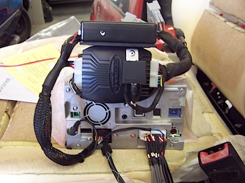
All the wiring is tidy: easy for maintenance and any enhancements.

Here’s one view of the wiring behind the head unit. The nylon mesh along with shrink wrap tubing is a quality of keeping wire harnesses together.

Here’s another view. You can see the original and the additional wiring.
Corvette Z06 Stereo install
October 28, 2010 § Leave a comment
Late last year, after buying a new-to-me 2007 C6 Z06, I took the car over to William Fonseca at 1Off Rides. William has done several installs for me, and wanted to show off his new brand of gear: Hertz. He took detailed photos of his whole install process, so I’ll show off some of his work across a few blog entries over the next couple of weeks.
I gave William two requirements:
- The system couldn’t cut any wires to install. I wanted to be able to return it completely to stock for resale.
- The sub and amp had to be removable for track use.
William did that, and added one of his own: when the sub and amp are removed, the system still plays! He put audiophile relays in all the speakers and connected both to the big Hertz amp and to the head unit: a Pioneer AVIC Z110BT. The sub and amp are removable with two mil-spec connectors and two nuts. They float in the back of the car: that is to say: they don’t touch the carpet. So when you remove them, there’s no matted down carpet.
All in all, William and his shop did a fantastic job with the install. Here’s a few pics for now:

The Hertz speaker is mounted to an aluminum adapter.

Here it is mounted to the door.

The GM LAN interface module and main power relay, along with the splice harness.

The mil-spec connector for the amp. It’s a simple pull to disconnect.
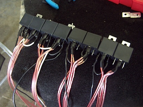
Just a few of the relays needed to allow the dual mode system to work seamlessly.
